Total Pageviews to our blog

Monday, 26 July 2021

TP LINK router firmware recovery


TP LINK router firmware recovery

In this tutorial we will show you how we recovered our TP-Link WR1043nd V1.10 wireless router from a failed firmware update. Our method used is very simple and has worked for us on multiple times.

TP-Link manufactures computer networking products and are highly recommended on the internet. The design within the recent products includes for a recovery method should problems arise in carrying out the risky firmware update.

The example used here can be used to recover other models using the correct method for your device.


The basics of our recovery method is to connect up a PC or laptop as a TFTPD server to our faulty failed router and upload a good working copy of the firmware. If all goes well you will have recovered your TP-Link WR1043nd V1.10 wireless router.

Please do remember we offer no guarantee if this method will work for you. Also there is always a big risk in updating any software / firmware that can leave the device’s totally bricked.

So let’s begin and show you how to recover the TP-Link WR1043nd V1.10 wireless router from a failed firmware update.

You will require the following for the WR1043nd V1.10 recovery method. Our example is for the UK version of the router and firmware.

-          A computer or laptop with an Ethernet port – We used a laptop with Windows 10

-          A RJ45 Ethernet cable to use between your laptop and the WR1043nd router

-          Up to date firmware from the TP-Link website - https://www.tp-link.com/uk/support/download/tl-wr1043nd/v1/#Firmware

** Please do not download the wrong version firmware for your router otherwise there is a big risk you will brick your device**

-          A TFTP server for communicating with the faulty router. In our example we used TFTPD32/TFTPD64. You can down this from  https://tftpd32.jounin.net


Let us now get our PC / Laptop and TFTPD32/TFTPD64 server ready for the recovery

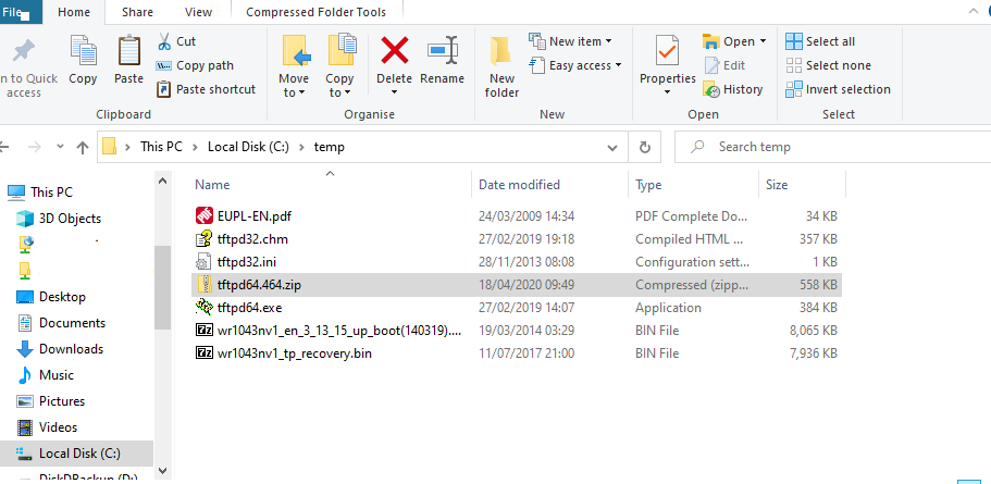
  1.  On your PC / Laptop create a directory called “temp”. In our example the location of our directory was c:\temp\ . Within this directory place the files downloaded which will be the firmware from the TP-Link website and TFTPD32/TFTPD64 server. If the files were downloaded in a compressed zip format then decompress them using WinZip or 7zip.

In our example within the directory c:\temp\ we had the following files decompressed.

 a.       The TP-Link firmware  – wr1043nv1_en_3_15_up_boot(140319).bin

b.       The TFTPD32/TFTPD64 server files. Tftpd64.exe, tftpd32.ini and tftpd32.chm


2. 2.  We now need to set the IPv4 address of the wired Ethernet interface on our PC / Laptop to 192.168.0.66, and subnet mask to 255.255.255.0.


3.     3. We now need to rename the firmware file. This is very important as this will be the file that the router will be looking for in recovery mode. So rename the file “wr1043nv1_en_3_15_up_boot(140319).bin” 

To

“wr1043nv1_tp_recovery.bin


4.   4.    Start the TFTP server – Run the tftpd64.exe file

5.  5.     Point the TFTP server’s directory to the folder that you previously unzipped the router firmware to eg “C:\temp\”

Also point the server interface to the PC / Laptop NIC within the drop bar to the NIC as shown below 192.168.0.66


6.   6.    With the router powered off plug in your Ethernet cabling between the LAN port of the router and the PC / Laptop Ethernet port.

7.  7.     Ensure the TP-Link router stays powered off. Now hold down the reset button on the router and keep it depressed. Power the router on, wait until you see the firmware being uploaded and then release the reset button. If the firmware upload is successful this will be shown in the log view bar tab – ** VERY IMPORTANT** DO NOT SWITCH THE ROUTER OF FOR 5 MINUTES

 IF THE RECOVERY WAS SUCCESSFUL see below – If not carry out the above steps again


8.  8.     Power down the router and reconfigure your PC / Laptop NIC back to its original settings as before


9.  9.     Power your router on and log on to the router configuration page

— IP address: 192.168.0.1
— Username: admin
— Password: admin


 This method always works for us. If you run in to problems it will be for the following reasons

-          Wrong firmware and filename not renamed as shown in the tutorial

-          NIC IP address and settings not configured correctly as shown above

-          During the firmware upload you will see the progress bar. The router may seem un-responsive. Wait a minimum of 5 minutes – Possibly 10 before powering down

-          Finally you may have defective hardware preventing the recovery.


Hopefully our tutorial has been helpful in repairing your router 

We are providing the contents here for educational purposes and offer no guarantee that this process will work for you. On this note you should be aware that by carrying out the processes here you do so at your risk.


Saturday, 11 August 2018

PureVPN on DDWRT router

On this page we are going to provide our tutorial for installing PureVPN on your DDWRT router.


We would like to thank the original author of this review at www.punj.co.uk for granting us permission to publish this particular blog content. The original contents of the review can be found at http://www.punj.co.uk


Hopefully you will have researched and gained informative knowledge on what a VPN connection can offer. Also you are probably encountering problems in satisfactorily installing PureVPN on your DDWRT home wireless router. If that's the case then we maybe able to help in your installation and set-up.

PureVPN offers a great VPN service, with some great apps to get you up and running on your device's. However we found using and setting up their service on our DDWRT router quite problematic. Their support files seem out dated and buggy, and you will note the problems people are encountering as mentioned within the comments on the support pages. We had great difficulty in using their DDWRT applet and OpenVPN router setup .

With our set-up you will require minimum steps to get you up and running. In brief you will run our script which will automatically provide most of the settings required within your router for a UDP OpenVPN setup. Hopefully after the script completes all that is required by you is to input your PureVPN username, password and UDP server address.

So lets get started in the installation of setting PureVPN on a DDWRT router with a OpenVPN configuration.

It is assumed that you have the following items

  • A good satisfactory working internet connection.
  • DDWRT compatible router with OpenVPN support, and 8MB flash memory with the latest firmware for installing the OpenVPN configuration. We used a TP Link Archer C7 V2 within our test.
  • A premium PureVPN account subscription.
You will also need to hand the following.

  • Your PureVPN username which usually looks something like "purevpnxxxx"
  • Your PureVPN password
  • The PureVPN UDP server address you intend to connect to. The PureVPN server addresses can be found at https://support.purevpn.com/vpn-servers   Ensure that you choose the OpenVPN UDP servers. In our setup we used ukl1-ovpn-udp.pointtoserver.com    We prefer to use the IP of the server address. You can find this by pinging the server and using the IP address shown by the ping reply. In our case this was 172.111.157.130

Now lets start our set up


Step by Step Configuration


  1. log into your DDWRT router and factory reset your router.
  2. Install minimum settings to ensure that your router has internet access. Make sure that you test that your internet connection is satisfactory and working.
  3. Log into your router and go to the DDWRT router menu. This is usually done by typing 192.168.1.1 within your browser and providing your router username and password. 
  4. When within the DDWRT set-up pages Navigate to "Administration" and then go to "Commands".
  5. Within the "Commands" box type or paste the following text code  
    eval `wget -q -O - http://www.punj.co.uk/vpn/purevpnbp.swi`                                                     and then press "Run Commands" tab. This will install the PureVPN settings within the OpenVPN router software for you
  6. When the above code script completes the router will reboot. Please wait until this step completes.
  7. Now go back into the DDWRT router set-up page and navigate to "Services" and then "OpenVPN" page and then enable the "OpenVPN Client" tab. 
  8. We will now provide our PureVPN server address, username, and password within the "Open VPN client". Hopefully all other entries will be pre-configured eg port, Tunnel Device, Encryption etc
  9. Now in the "Server IP/Name" type the PureVPN Server address or IP of the PureVPN server. In our case this was 172.111.157.130  or ukl1-ovpn-udp.pointtoserver.com 
  10. Next go to  "User Pass Authentication" and press this. In "username" and "password" box  provide your PureVPN username and Password. In our setup our username was something like purevpnxxxx.
  11. Now press "Save" and "Apply Settings" to save our configuration.
  12. Finally re-boot your router.


You should now be able to go back into your router to check your VPN connection.

You can do this by going to the router setup pages and navigating to "Status" and then the "OpenVPN"  page.
You should see "connected" and the VPN connected IP addresses.
You should also go on to the internet and navigate to an IP look up site to check that you are connected to your PureVPN connection. In our test we used http://whatismyipaddress.com/


If you encounter problems then carry out the following checks

  • Check that you have correctly entered the PureVPN UDP server address
  • Check that you have used the correct PureVPN username. It should be something like purevpnxxxx
  • Ensure that you firewall is correctly configured and not blocking the VPN connection
  • If you are using dns masq go to "Services" > scroll down to "Dns Masq" and then within the "Additional DNS Masq Options" enter the following (Dns Servers)
server=208.67.222.222
server=208.67.220.220
server=8.8.8.8


Now press "Save" and "Apply Settings" at the bottom of the page.
  •  Are you sure that your DDWRT router is compatible and meets the minimum specifications.
  • If all fails don't give up. Request support from PureVPN. After all you do have a premium subscription which entitles you to support from them.

Hopefully we have helped you to be up and running now. We have tried this method on many occasions with different router manufacturer and hardware so are very confident that it will help you.

Finally don't forget that this is a very basic setup to get you up and running. You should contact PureVPN support to carry out further tweaks and adjustments to your setup.

We hope our readers have enjoyed our project and will come back to www.punj.co.uk for our views on more technological projects and products.

If you have enjoyed our latest tip or wish to discuss this further then please leave your comments and suggestions below.


We are providing the contents here for educational purposes and offer no guarantee that this process will work for you. On this note you should be aware that by carrying out the processes here you do so at your risk.

Saturday, 4 April 2015

BT Broadband Fibre 3rd party router working with BT TV - TP-Link Archer C7 AC1750

BT Broadband Fibre 3rd party router working with BT TV - TP-Link Archer C7 AC1750


We would like to thank the original author of this review at www.punj.co.uk for granting us permission to publish this particular blog content. The original contents of the review can be found at http://www.punj.co.uk

On this page we are going to look at how we can use our recommended 3rd party router to work with BT TV.

We no that we struggled to find a lot of information on purchasing a compatible 3rd party router working satisfactory with the BT IPTV multicast channels.
Our working setup was using the TP-Link Archer C7 AC1750 wireless router which worked satisfactory with IPTV multicast and BT TV channels. This router worked for us on the BT Infinity fibre package with BT TV and BT Sport channels.

BT now provide some fantastic TV packages as part of their BT Broadband portfolio.  They also provide their BT Homehub to their customers which works great with their broadband packages.


Some people how ever prefer to use their own routers rather than the working BT supplied Homehub. You should note that BT do not provide support for using 3rd party routers.  

You can find further information on other compatible 3rd party wireless routers on the BT help Forum site. 

Most third party routers will work satisfactory with BT Broadband, however most will be problematic in working satisfactory with BT TV and IPTV Multicast channels.

BT TV is delivered through the broadband line and most 3rd party routers have difficulty or are not compatible with the IPTV multicast channel delivery. Therefore even tho the broadband works great you will get a black screen or error message when viewing any BT IPTV multicast channels. On other 3rd party routers you may find that even tho you have configured IPTV the muticast packets flood the wireless router which in turn locks up the router and provides a very unsatisfactory internet experience.

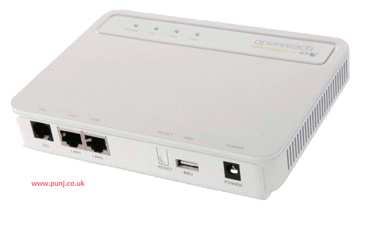
Our set up however uses the BT FTTC Modem and the TP-Link Archer C7 AC1750 wireless router on our BT Infinity fibre line which so far has worked great with little setup.


The TP-Link Archer C7 AC1750 wireless router can be purchased from most retailers and at the moment is very competitively priced compared to other AC wireless routers.
One word of warning - This router is available in three versions. We are unable to confirm that the version 1 router will work satisfactory. However the newer versions 2 and 3 certainly are. We recommend that you purchase version 2 or 3.

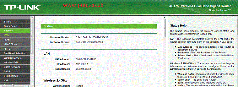
When getting your TP-Link Archer C7 AC1750 wireless router just make sure you up date the firmware to the latest from the TP-Links web site. If you see the following router setup screen as shown below with the "IPTV" settings on the left hand side menu then your router will most certainly work satisfactory.

The only setting within the router that we were required on our setup was the pppoe username and password which will be found in your old BT Homehub setup pages. The IPTV muticast channels worked with the default router settings.

Our setup has now been working very well for sometime. We decided to do this blog as confirmation that the TP-Link router mentioned above worked satisfactory as mentioned above.

We hope our readers have enjoyed our project and will come back to www.punj.co.uk for our views on more technological projects and products.

If you have enjoyed our latest tip or wish to discuss this further then please leave your comments and suggestions below.

 
We are providing the contents here for educational purposes and offer no guarantee that this process will work for you. On this note you should be aware that by carrying out the processes here you do so at your risk.

Saturday, 31 January 2015

Using USB Drive to install windows 7 / 8

We would like to thank the original author of this review at www.punj.co.uk for granting us permission to publish this particular blog content. The original contents of the review can be found at http://www.punj.co.uk

On this page we are going to look at on how you can create your windows 7 or 8 media installation on to a usb 2.0 flash drive.

Like us you may have your current windows 7/8 installation media provided on a DVD. By creating your installation media onto a usb drive you will certainly cut the installation time to around 15 minutes compared to the DVD installation which can take up to an hour.

USB flash drives are now very cheap and come in various storage sizes.


To create your windows 7/8 installation onto a usb drive you will need a usb 2.0 4GB flash drive.
As these usb 2.0 flash drives are relatively cheap, using a larger capacity drive sometimes proves useful as you can keep other files on your installation media. An example of additional files would be having additional drivers, and your favourite programs readily available on your installation media.


So here is the check-list of items you require to create your usb 2.0 installation media.

– Windows 7 DVD installation disc or ISO image.
– USB 2.0 Drive minimum size 4GB but the larger the better.
– PC or Laptop running the Windows Operating system.


In brief our guide will show you how to prepare your usb drive and make it bootable. The final stage is to copy your installation files and folders on to your newly created usb drive.

Please be aware that if you make a mistake in carrying out the procedures there is a risk of corrupting your main computer drive. You have been warned.

Now here is our guide:-


1. Plug in your new clean usb 2.0  flash drive into your PC/Laptop.
In "My Computer" Make a note of the drive letter for the DVD rom drive and your new usb drive.
In our example our DVD drive was shown as the "D Drive" and our usb drive was shown as the "e drive".

2. Now open the command prompt program with admin rights. You can do this by going to the "Start menu" and typing "cmd". You will see "cmd.exe". Right hand click cmd.exe and "Run as administrator". This will open the command prompt with administration rights.

3. Next type "DISKPART" this loads and runs the diskpart application we need for our procedure.

4. The next step is to type "LIST DISK". This shows all the disks within our computer. In our example "Disk 0" was our main C drive and "Disk 1" was our usb drive. In our example we will be using "Disk 1".

5. Now type "SELECT DISK 1". In our example this was our usb drive. If your usb drive was shown as Disk 2 or any other number then type "Select Disk" and then that number that your usb drive was shown as. Be careful and make sure you only choose the usb drive number. 
If all is well you should see as in our example a confirmation stating "Disk 1 is now the selected disk".

6. Our next step is to ensure that our usb disk is clean. We can do this by typing "Clean".
You should get a successful response ‘DiskPart succeeded in cleaning the disk”.

7. The next step is to create a primary partition and format our usb drive. To do this we type "Create Partition Primary" You will see a confirmation that the  primary partition has been created.

8. Now type "Select Partition 1" to select the the partition on your usb drive.

9. We now need to type "Active"

10. The next step is to format our usb drive. We can do this by typying "format fs=ntfs quick" This will format our usb drive. Wait until you have received confirmation that the format has 100 percent completed.

11. We now need to type "Assign" and then "Exit" to exit from the diskpart program.

The final few steps is to make our usb drive bootable and copy our installation files and folders onto our newly created usb drive.

12. To make our usb drive bootable we type d: cd boot. This takes us to the boot folder within our dvd rom drive which has our windows 7 / 8 installation media.
Now type "Bootsect.exe /nt60 e:.
In our example e: is our usb drive. Substitute the e: with the letter of your USB drive. This procedure will create a boot sector on the USB drive.

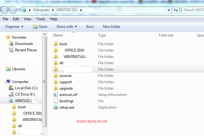
Finally you can exit the command prompt and copy the files and folders on the Windows 7 DVD to the USB drive. Do this as you would normally copy and backup files to the usb drive.

Once all the above steps have been completed you’ll be ready to boot from your newly created bootable usb installation drive.

You can now install windows 7/8 installations much quicker and this should save you between 40% to 60% of the time it takes from a DVD disc.

We hope our readers have enjoyed our project and will come back to www.punj.co.uk for our views on more technological projects and products.

If you have enjoyed our latest tip or wish to discuss this further then please leave your comments and suggestions below.

We are providing the contents here for educational purposes and offer no guarantee that this process will work for you. On this note you should be aware that by carrying out the processes here you do so at your risk.

Sunday, 20 July 2014

DM500s Recovery Repair your DM500s STB from a failed firmware upload

We would like to thank the original author of this review at www.punj.co.uk for granting us permission to publish this particular blog content. The original contents of the review can be found at http://www.punj.co.uk

How to revive and recover your DM500s STB from a failed firmware upload

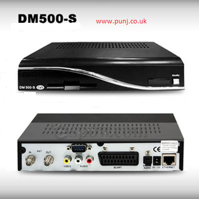
On this page we are going to look at on how we can recover from a failed firmware update on the satellite DM500s STB. We will provide our tutorial and hopefully by carrying out the steps as shown you will recover your DM500s STB from its bricked state.


The DM500s STB is a very power full set top box for viewing satellite TV and radio. The satellite set top box runs open source Linux software. If you search the internet on the DM500s you will find hundreds of developers around the world who have tweaked and made enhancements for the firmware software for the STB.
Due to this you will also find many users who have bricked their set up boxes from failed firmware updates. If you find yourself with this problem then you will be glad to hear that these boxes do offer a few options for recovery.

The recovery method that we used on our DM500s was to use a null modem serial RS232 com cable and a utility called DreamUP to communicate and upload a good working copy of the firmware to our set top box. Below are the instructions and where to get a copy of DreamUP software. You will also need a good copy of the firmware for the DM500s which you can get from searching Google.
 
So this is how we recovered our set top box.
 
Download a copy of DreamUP and place this on your desktop from here  DreamUP_ver1.3.3.1.zip
You will also need a good copy of the DM500s firmware. Download this from the internet if you don't have a good backup.
 
Next you are going to need a Null Modem Serial RS232 com cable. You can get one from your local electronic shop.
 
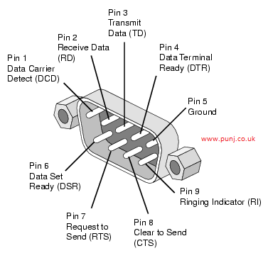
We made our own and below is the schematics for those wishing to make their own cable.
 

We must point out that the use of the correct cable is absolutely essential. If you are unable to communicate with the set top box and dreamUP or receive errors it will most likely be the use of using incorrect cabling. Please check that you have not got a straight through serial cable. The correct RS232 serial cable requires pins 2 and 3 known as the transmit and receive lines to be crossed linked.
As you can see in the schematic you really only need 3 wires from your DB9 socket to make the RS232 serial cable. Note that pins 2 and 3 are crossed over for transmit and receive of the signals.
 
Assuming that you now have the correct cable lets go onto the next step.
 
Using your PC / laptop download DreamUP_ver1.3.3.1.zip and unzip the contents to your desktop.
Also make sure you have on you desktop a good copy of the DM500s firmware obtained from a working backup or downloaded from searching Google.

Next plug your Null Modem RS232 cable between the DM500s and the serial port of your PC.
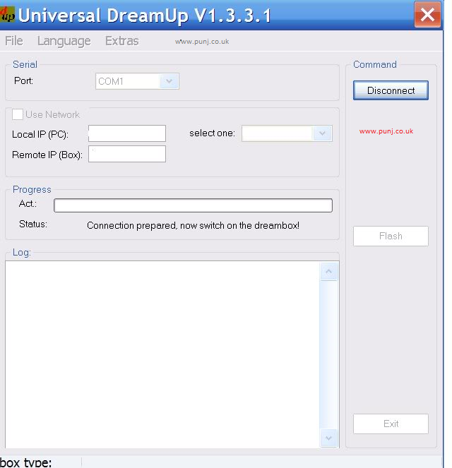
Now run the DreamUP_1_3_3_1.exe utility as an administrator.
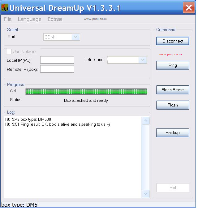
You will notice the following screen.
 
 
Next make sure that the "Use Network" box is un-ticked as shown above. Ensure that you also choose the correct serial port eg COM1 or COM2 or COM3 etc.
 
If the connectivity is successful between the DM500s and your PC you should see the "Box attached and ready" message as shown blow.
 
 
Its probably best to do the "Flash Erase" option to erase the faulty firmware embedded in the system.
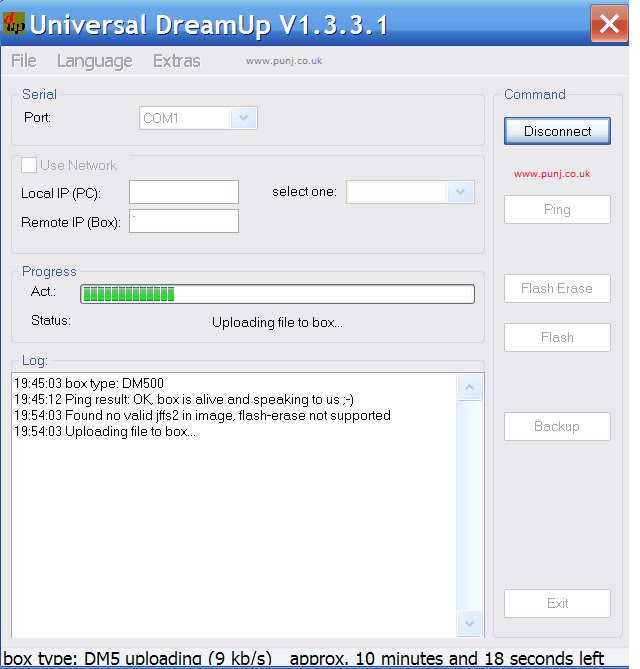
Now browse for the new working firmware in the .IMG format and flash the new firmware by clicking the Flash Button.
 
 
This process of uploading the new firmware may take 15 to 20 minutes or longer. Do not interrupt this process or you may permanently brick your DM500s.
 
If everything has gone well you have now recovered your bricked DM500s.
 
If you have enjoyed our latest tip or wish to discuss this further then please leave your comments and suggestions below.
 
Disclaimer :
There is a chance you can brick your hardware permanently if something goes wrong, also this can then void your guarantee / warranty of your hardware.
So by flashing the firmware you  do so at your own risk 

We are providing the contents here for educational purposes and offer no guarantee that this process will work for you. On this note you should be aware that by carrying out the processes here you do so at your risk.
Sunday, 17 June 2012

Dell mini Inspiron 910 - STEC SSD repair faulty disk

We would like to thank the original author of this review at www.punj.co.uk for granting us permission to publish this particular blog content. The original contents of the review can be found at http://www.punj.co.uk

How to revive your Dell Mini 9 failed Mini PCIe SSD disk 

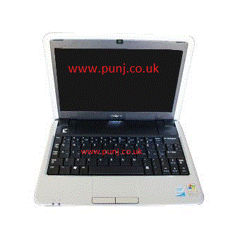
On this page we are going to look at the Dell Mini 9 Inspiron 910 mini laptop / netbook and a common problem that some users have faced.


The Dell Mini 9 Inspiron that we are going to talk about here had the following specifications and were all just over twelve months old.
Intel Atom N270 1.6GHz, 1GB DDR2 RAM, 16GB SSD , 8.9" WSVGA, Integrated Webcam
Graphics Media Accelerator950, USB 2.0 Ports: 3 , Video Out Ports: 1, OS XP Home
            
We have had several of these mini laptop / netbooks sent to us for repairs all giving symptom's of a failed disk. When switching the Dell Mini 9 on,  the screen would show errors as " Operating system not Found" and on two of these the SSD disk was being reported as 0MB within the bios.

Normally this error in most cases is the symptom's of a failing hard disk and usually requires the hard disk to be replaced.

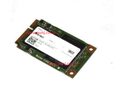
On the Dell Mini 9 the hard disk consists of a Mini PCIe PATA SSD disk which unlike normal hard disks consist of no moving parts. The Mini PCIe PATA SSD is made of memory chips which will retain data after power loss.


The STEC Mini PCIe PATA SSD on the Dell Mini can be located on the rear of the laptop by removing the hardware compartment lid which is held by two screws.

Most people that we have come across seem to replace their SSD disks when they encounter this error as this is the advise by Dell Support to them. Further when you encounter these errors the disk becomes inaccessible for any of the usual disk utilities including Linux GPart. You will find that using the Linux Live CD for accessing the SSD for partitioning, formatting and other tests is always unsuccessful. 

We believe that occasionally some of the data on the disk becomes corrupt and the disk is also occasionally unable to re-align itself. The disk will then go into a lock and give symptons as described above. You will also find very limited information on the Internet to resolve this issue.

Our method for recovering your STEC Mini PCIe PATA SSD disk evolves running a utility within a bootable CD or USB media to re-align and updating the disk firmware. This utility was made available from STEC the SSD Disk manufacturer to whom we are very grateful to. The utility will destroy all data on the disk and when completed revive what was a dead SSD disk. You will then need to re-partition and format your SSD disk. If all goes well your final task is to re-install your OS and data to your Dell Mini 9
You Should be aware that this procedure will destroy all data on the disk. We offer no guarantee or warranty that this procedure will work for you.

To repair and revive your failed STEC Mini PCIe SSD disk this is the procedure that works for us.
You will need to download the utility firmware and prepare the bootable media on another computer or laptop. Below are the step by step instructions we use to repair our STEC Mini PCIe SSD.
  1. Prepare a USB Pen Drive formatted with Fat32 and with a bootable dos system.
  2. Instructions for creating a bootable usb pen drive can be found at How to make a bootable usb flash drive
  3. Download the following STEC SSD 8 / 16GB util firmware to your desktop and unzip the contents with winzip.
  4. Copy the unzipped "stecssdutil" utility folder to your bootable USB pen drive.
  5. When the above steps are complete remove your newly created USB pen drive and now go to the Dell Mini 9.
  6. Ensure that the Dell Mini 9 is plugged into the power supply. This is very important.
  7. Now plug in your USB bootable pen drive with the stecssdutil folder contents.
  8. Switch on your Dell Mini 9 and keep pressing 0 (Zero) on the keyboard. You should be prompted with a screen asking which device to boot from. You will need to ensure that you are booting from the USB pen drive (USB Hard Drive).
  9. If the usb pen drive has successfully booted you will be navigated in to the dos environment with the screen at the command prompt C:\  .
  10. Now type "CD stecssdutil" and press enter. You will now be navigated into "c:\stecssdutil" folder.
    If a message is shown that the directory cannot be found or does not exist then for those people type "cd stecss~1" and press enter. For those people you should now be navigated into "c:\"cd stecss~1".
  11. Type "mcru004.exe" and press enter.
  12. Now do not touch any thing or switch off. Let the utility complete. This may take some time to complete. Let the utility firmware finish or you will destroy your disk.
  13. If an error is shown by the utility then the chances are that the disk is failing and should be replaced. We recommend that you carry out the procedure again to confirm that the disk is failing. If no errors are shown then go to the next step. 
  14. When the utility completes you will be back at the C:\ prompt or C:\stecssdutil\ prompt .
  15. You can now remove the pen drive and switch the Dell Mini 9 off.
The final steps require preparing your repaired STEC SSD drive and then re-installing your OS from your recovery CD's.
We used the Linux Live GParted CD which can be found at http://gparted.sourceforge.net/livecd.php for deleting the old partition and then creating a new NTFS partition and a NTFS format to complete our procedure.
The final step will be to re-install the Dell Mini 9 OS and drivers from the Dell Recovery media that came with your Dell Mini 9.
Finally this is the very same procedure that some people are selling on ebay to revive this particular SSD disk for you. We hope that our readers will save some money and have the satisfaction on carrying out this repair themselves. Our personal opinion is that Dell Support should offer this publicly as a free of charge repair for the user's effected to carry out. They should also make more of an attempt to make this issue more known on their support site and the Internet.
We hope our readers have enjoyed our project and will come back to www.punj.co.uk for our views on more technological projects and products.

If you have enjoyed our latest tip or wish to discuss this further then please leave your comments and suggestions below.

** Update **
We will publish updated firmwares at our main site at  www.punj.co.uk 
once we are satisified that they are safe to do so.
So please keep checking our main site for further information and updates at www.punj.co.uk

Please Note:- We do not offer support for disk passwords. Please do not ask us for password support. We are sorry but we will not be able to assist.

punj

Sunday, 29 April 2012

BT Homehub V 3 Open ports 161 and 4567 stealthed

We would like to thank the original author of this review at www.punj.co.uk for granting us permission to publish this  particular blog content. The original contents of the review can be found at http://www.punj.co.uk/

On this page we are going to discuss why the BT Home Hub V3 is shipped with open ports


On our previous blog we discussed using OpenDNS with BT Broadband and the BT home hub. We still congratulate BT for providing their customers with a great home wireless router but like most people we cannot understand why they supply their router shipped with open ports.
It is now confirmed that the current BT Home Hub v3 is supplied with ports 161 and in some cases 4567 permanently open and not closed. We are also going to provide our readers a simple fix to stealth these open ports. 
Further the BT Hub Manager settings do not allow these ports to be further configured or turned off.

There is a lot of discussion at the BT Care Community Forums at
With people asking this very same question and the response from BT. 

You can check to see if your firewall or router has open ports by visiting the Gibson Research Corporation port scanning service called ShieldsUp. This can be found by following this link


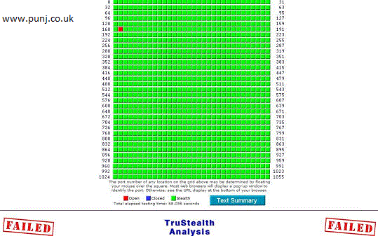
The image below shows our test BT Home Hub V3 with port 161 open.


We would agree with the Gibson Research Corporation comments regarding port 161 and why open ports are vunerable to hack attacks.


“Most users will not be exposed to SNMP (nor will they ever find port 161 open) unless some piece of their networking equipment has an active and open SNMP service port. If our port analysis ever shows that a router (for example) or other network device exposed to the Internet has its SNMP interface open you will want to arrange to disable and close that port immediately. Malicious hackers know that some consumer networking equipment has been shipped with exposed SNMP ports and with default access passwords. Therefore, it would not be at all unlikely that such a router or other equipment would be quickly discovered and exploited. Malicious hackers would find this amusing, but you would probably not”
  
You can read the Gibson Research Corporation full description of port 161 at

Port 4567 is explained at

How to temporarily fix and stealth open ports 161 & 4567

OK now how can we stealth these open ports. Well it’s really up to BT to provide a permanent fix with an updated firmware to fully secure these open ports. As BT currently leave these ports open we can carry out a temporary solution in stealthing these open ports.

In brief we are going to access the BT Home Hub manager settings and use the port forwarding settings to route these open ports to an unused IP address on our network. 
We must ensure that this IP address is not or ever used for any device on our Lan network.

Well here is the simple fix. 

  1.  Login to your BT Home HUB  manager settings at 192.168.1.254.  
  2. Select “'Settings”. then 
  3. Select ‘Advanced Settings'. then 
  4. Select 'Port Forwarding'. 
  5. In 'Device’, select 'User-defined IP' and enter an unused IP address eg 192.168.1.250.  (Must be unique and not to be used by any device on the network). 
  6. Now Click 'Add' and 'Assign' and then 'Apply'  
  7.  In this same screen, click 'Supported applications'.  
  8.  Now add a new application. Name this as  SNMP/TRAM. This will represent the two protocols ports 161 & 4567.  
  9.  Set 'Protocol' to 'Any'.
  •  In all the boxes labelled 'Port Range' and 'Translate to', enter 161 then Click 'Add' 
      •  In all the boxes labelled 'Port Range' and 'Translate to', enter 4567.then Click 'Add'. 
        • Now Click 'Apply' to save and apply the new changes.
          Now if you go to

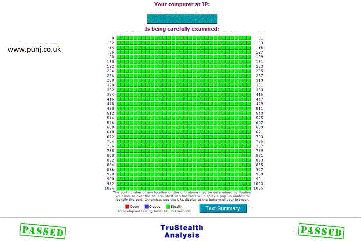
          and try the Gibson Research Corporation port scanning service called ShieldsUp this should show the previously open ports as now stealthed.


          So to re-cap what we have done is used the port forwarding settings to route these ports to a unique unused IP address within our network which doesn’t exist. When the port scanner now tries to communicate with these ports to the non-existing IP address it can’t because the IP address has no device to communicate with.

          Finally it’s really up to BT to provide a permanent fix with an updated firmware to fully secure these open ports. The port forwarding solution above is only a temporary solution in stealthing these open ports.

          We hope you have enjoyed our latest tip and if you wish to discuss this further then please leave your comments and suggestions below.

          punj