IP Bullet camera night
vision repair
In this tutorial we will show you how we repaired our IP CCTV camera which would not illuminate the night-time infra-red LED’s. This meant that although our IP Camera worked during daytime our faulty CCTV camera would not provide video or images during the dark night-time hours. At night-time only a black image screen was seen and observed.
Please note that the human eye cannot see the infra-red light illuminating. We used an old mobile phone camera which could see the infra-red light to check whether our IP camera was illuminating it’s infra-red LED’s.
Our camera was a cheap ebay IP bullet CCTV camera.

Once we were satisfied
that the software was up to date it was time to check the camera PSU to ensure
that this was not faulty. We had a spare new good 12V 1.5A power supply which
proved that the camera had a good power source.
The next step was to
take the camera apart to inspect the internal components and hardware.
Now as part of our diagnostics we had to be careful when powering the camera in its tear down dismantled format as not to short the circuit boards or internal components.
We checked that the CCTV camera was clicking when covering the camera or in darkness. This told us that the camera was trying to go into night-time vision mode. This could also be done by covering the light dependent resistor. (Location of the LDR as shown in the picture image below).

We also used an old phone camera which could show whether the infra-red LED’s were illuminating. How-ever in our case our Infra-Red LED’s were not illuminating.

Our next step now was to check and test each diode on the LED array circuit board. Our chosen method to do this was to use a multimeter with a diode test function mode.

This test would be carried out with the Infra-red array board disconnected from the camera and any power supply.
Our Infra-Red array
board had 24 IR LED’s. A good IR LED reading with our multi meter would show a
volt drop reading of approx. 1.2v in one direction only. When reversing the
leads the meter should display open circuit.

Testing each LED on our IR LED array board
Using our multimeter with the rotary dial on the diode test function we tested each LED as follows
Connect the test leads to the LED. A good LED test showed a reading of approx. 1.28v.
When the leads are
reversed the meter should display OL or open circuit.

In our case we found that 4 of our infra-red LED’s were open circuit testing both ways. This indicated that these LED’s were bad and faulty. We now had to un-solder the suspect faulty LED’s from the array circuit board.

Our next step was to either order spare good infra red LED’s or find a replacement 24 infra red LED array board to replace our faulty one.
Replacement spares as mentioned above are cheaply available from ebay.
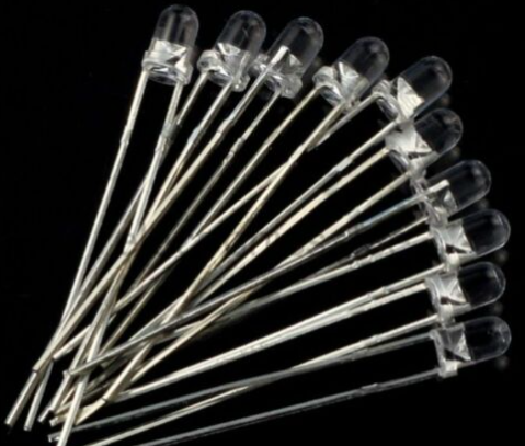
We decided to replace the individual 4 faulty IR LED’s. We ordered 5mm 850nm Infra-Red LED’s to replace our faulty ones.
Our new IR LED’s were soldered back to our circuit board observing the correct polarity.
We re-tested all the infra-red LED’s on our board as mentioned above with our multi meter before
re-assembling.
Finally our IP CCTV Camera was re-assembled and powered up to prove that our repairs were carried out successfully.

Our IP camera has been
re-installed and has been working great since our repairs.
Hopefully you have found our tutorial of interest and may be of help to you.
We are providing the contents here for educational purposes and offer no guarantee that this process will work for you. On this note you should be aware that by carrying out the processes here you do so at your risk.