Total Pageviews to our blog

Sunday, 15 January 2012

Solve wireless router connection problems

We would like to thank the original author of this review at www.punj.co.uk for granting us permission to publish this  particular blog content. The original contents of the review can be found at http://www.punj.co.uk/

Many people today connect to the Internet using a wireless router either provided by their ISP or purchased by themselves.  Wireless routers are great devices letting people connect to their home networks without having a wired connection between the device and the router. As an example you can sit in your garden and connect wirelessly to your home wireless router to access the Internet.


We have come across many occasions when the wireless router sometimes becomes problematic and intermittently disconnects the user providing an unsatisfactory connection. To help we are going to give our readers some useful tips on how to resolve these issues.

You may have experienced one of the following symptoms:

1. Your PC or laptop frequently connects and disconnects you from the wireless router.
2. You are connected to your wireless router but the wireless connection seems very slow.

We have resolved these issues on many occasions by just following some simple tips.

Some useful tips to resolve wireless problems

Nearly all wireless routers today come preset so that the user simply connects their wireless router to the ISP connection and by using the security key provided they are ready to surf the Internet.
The security key will normally be found on a sticker on the back of the router.
The manufactures try very hard to make the installation of the wireless router an easy experience for the user.
An example of this setup by the manufacturer would be that the wireless router comes pre-configured with the wireless channel pre-set to "Auto" or Channel "6".
Normally in all occasions an unsatisfactory wireless connection is due to external interference interfering with the wireless connection.
The external interference can come from neighbouring wireless routers and devices. Indeed even the neighbours microwave can interfere with your wireless connection.
A simple solution to resolve and fix your connection is by changing the channel your wireless router uses to communicate with your devices eg computer or laptop.
To change the channel you will need to go into the wireless router set up pages. You can find more information on how to get into your wireless router setup pages by reading your router manual or by searching in google for your router.
Once you are in the wireless router setup page you will notice that the wireless channel is set to "Auto" or channel "6". This channel setting can normally be changed. You can normally manually set the channel number between 1 to 13.
By simply changing this to say channel "2" you can resolve a lot of issues. You may even find that your wireless router can now be picked up at longer distances and stay satisfactorily connected for a longer time.


Some of the more experienced users will also tweak their devices in other ways in an effort to get the best wireless connection. How ever some of these tweaks can also result in making the connection unsatisfactory and even worse for the user. An example of this is one that we came across very recently.
We had a user who had the DD-WRT firmware on their wireless router. They were able to set the transmit TX power settings which basically either transmits the wireless signal at higher or lower power settings.
They thought by using higher power settings they were improving their wireless signal so that it would be picked up more easly by the wireless devices. However by setting this at higher power settings they were just saturating the signal to their wireless device. We recommend that you never increase the power transmit settings on your wireless router. Not only will you saturate additional noise but you will most probably shorten the the life of your wireless router. We were able to resolve this issue for this user by just lowering this slightly lower than the default setting. In our case this was lowered from the default setting of "70" to "50".

Some people will also access the wireless NIC settings within the wireless NIC device on the laptop or computer. Within the "Wireless Network adapter connection" you can get access to the wireless adaptor settings within the advanced menu. Here you can also see that on some wireless adaptors you can set the "Transmit Power". Some people think by setting this to the "Highest" setting they will be able to iimprove their wireless signal as it is now operating at the highest setting. All they are doing here is again shortening the life of their wireless adaptor and as stated before saturating the wireless signal. 
We again recommend that you choose a medium setting for the transmit TX setting.
The lower the setting the better the wireless connection will perform. Also the wireless NIC card will use less power which will result in less heat and a longer life for that device.

We are amazed that the tips we have detailed above are not given as standard by the manufactures support  personel.
We have come across many users replacing their wireless routers stating that the previous router that was purchased not so long ago as poorly made by the manufacturer. Indeed the same has been said for the free ISP supplied wireless routers.  In our opinion manufactures do try to make good quality products and ISP do want to provide the best for their customers. However by just changing the wireless channel will most defantly in most cases give amazing results.

Over the years we have resolved many wireless issues by just using the simple tips above.

So finally if your wireless router is playing up whether this is the one you purchased or this was given free to you by your ISP,  we recommend you try our tips here, Hopefully you will once again have your wireless router and devices working as they are suppose to.

If you have enjoyed our latest tip or wish to discuss this further then please leave your comments and suggestions below

punj

Saturday, 31 December 2011

Best Wishes for 2014 new year

Seasonal Greetings to all

Wishing everyone a happy new year for 2014
May the new year bring love happiness and peaceful living to all

Best Wishes from everyone
at
Punj Technology Blog
and
www.punj.co.uk

Friday, 19 August 2011

Toshiba Corrupt bios Recovery

We would like to thank the original author of this review at www.punj.co.uk for granting us permission to publish this  particular blog content. The original contents of the review can be found at http://www.punj.co.uk/


On one of our previous blogs we reviewed and demonstrated on how to recover your computer / laptop from a corrupt bios using the EPROM / EEPROM MCUmall True-USB PRO GQ-4X Willem Programmer 

Now we are going to show you how you can recover from a corrupt bios using no specialist equipment.

This method will require the use of a floppy disk media, CD/DVD or a standard usb stick flash media device. This method is commonly known as"Bios Crisis recovery disk method".

The bios is the first part of software code to run when you switch on a computer. This code gives instructions for the power on self test (post). This self test checks and ensures that the computer has all the required parts eg disks memory etc and that they function.

Most modern computer bioses can be recovered by using a crisis disk whether this be via a floppy or usb disk media. On some computers however when the bios boot tables become corrupt this can be problematic as this normally requires the bios chip to be manually reprogrammed or replaced. If your bios boot tables have become corrupt then this process will probably not be successful.

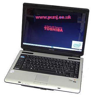
We were recently contacted by one of our clients who had corrupted the bios to his Toshiba A100-210 Model PSAA8E laptop.

Our client had visited the official Toshiba website and downloaded the bios for his laptop from here
He then carried out the procedure of updating his bios as instructed. 
The Toshiba bios program seemed to run and complete as confirmed at the end of the update. However when the laptop re-booted he noticed that the start up screen seemed to stay stuck on the blue bios start-up screen. He was then unable to get the laptop to progress further and boot to his windows xp installation.


There was a lot of private data which was now UN-accessible. In desperation the laptop was given to us to see if it could be recovered. We are not sure why the bios update had failed as our client seemed to suggest that he had carried the update as recommended.
 
We knew that this laptop has a Phoenix Bios so our first attempt was to try the bios disk recovery method. 

For this method which we have successfully used before you will need a usb floppy disk drive with 1.44M floppy media. You will also need to download files as instructed below. In brief we will create a recovery diskette which will have a good copy of the bios file. For this particular laptop a good copy of the bios file will be available within the download below.

This is a step by step instructions on how we carried out the bios disk recovery method.
  1. Download the BiosRocoveryMethod.rar file from here  This will have all the files required to create the floppy diskette and a good copy of the bios file for this laptop.
  2. Use winrar to decompress the downloaded file and place them in a folder on your desktop.
  3. Now you will need a floppy drive or usb stick. We used a usb floppy drive as we no from experience that the usb stick will be unsuccessful with the recovery of this particular laptop.
  4. You need to carefully read the instructions in the BiosRocoveryMethod folder downloaded earlier.
  5. You will now need to Click on the Phoenix_Crisis_Recovery.exe to make a bootable Floppy.
  6. Copy all the files from Rescue folder to your newly created bootable floppy diskette.
  7. Rename your BIOS file to bios.wph and copy it to your floppy diskette. We have provided a good copy of the bios file for this laptop.
  8. Now un-plug the power to your laptop. Connect your usb floppy drive to your usb port with the newly created bios recovery diskette.
  9. Hold down FN+F keys on the keyboard and while holding plug the computer in to the power and press the power button.
  10. You should hear the laptop bleeping and also the floppy drive being read and working. Hold the keys for a while and then let go.
  11. Leave the laptop for at least 10 minutes. Within this time the laptop may also repeatedly bleep whilst also copying the new bios file to your laptop.
  12. If the laptop does not restart itself after about ten minutes turn the power down and re-start the laptop
Hopefully the laptop will re-start and at the intial bios boot screen ensure that you set your bios to "Load bios Defaults".


Your laptop should now boot to your xp installation and hopefully you will have recovered from your corrupt bios.

A few words of caution. This method with the provided bios file is only for the Toshiba A100-210 Model PSAA8E laptop. Do not use this file if you are going to use this method for a different laptop / computer. If you do use this method for a different computer / laptop which has a phoenix bios be sure to use a bios file for that computer or laptop and re-name to bios.wph.

You should also be aware that updating the computer / laptop bios carries risks and could render your motherboard completely dead if things go wrong.

We are providing the contents here for educational purposes and offer no guarantee that this process will work for you. On this note you should be aware that by carrying out the processes here you do so at your risk.

We hope our readers have enjoyed our project and will come back to www.punj.co.uk for our views on more technological projects and products.

If you have enjoyed our latest tip or wish to discuss this further then please leave your comments and suggestions below.

punj

Sunday, 27 February 2011

Using OpenDNS with BT HomeHub Broadband

Using OpenDNS with BT Homehubs Broadband

We would like to thank the original author of this review at www.punj.co.uk for granting us permission to publish this  particular blog content. The original contents of the review can be found at http://www.punj.co.uk/punjwebfiles/telecom/bbrouterproblems.html

On this page we are going to show you how to use the OpenDNS service on BT Broadband using the BT Homehub and some additional cheap hardware. BT has currently disabled their users from entering their own dns settings on the BT Homehubs using the current BT firmware. BT had adopted to disable certain features on their homehubs to close certain security vulnerabilities on their hardware.

So first of all lets briefly find out what the OpenDNS service is.

OpenDNS is a dns service which can help in providing the user in controlling and blocking Internet sites which the user deems as inappropriate. This can be useful if you have kids on your home network and you want to filter and block web sites which you deem appropriate for them to visit or use.
OpenDNS also provides anti-phising and  malware / botnet protection to further protect the Internet user. We do however advise strongly that the user still incorporates security software on each PC / Laptop and home  network devices that they currently use to ensure a high level of protection.

Now we will give a brief explanation of the BT Homehub.
BT provide all their customers exclusively using the BT Broadband product their branded wireless router known as the BT HomeHub. In providing this great piece of kit  BT can provide support for the BT Broadband customer. The latest BT Homehub version 3 includes the smart wireless N technology, provision of a gigabit LAN port and the USB port for connecting a printer or hard disk to your home network. This version of the home hub can also be used on BT's ADSL and Infinity product. Overall we have been very impressed with this latest BT Hardware and congratulate them in providing such an outstanding piece of kit.


By using some additional hardware and setting the home network correctly we can use the OpenDNS service and still get support from the official BT support channel as we are still using their provided piece of kit on the BT Broadband product.

In order to use OpenDNS we need to configure the dns settings on our home network to use the OpenDNS servers. This can be done in a couple of ways. The user can either at each computer or laptop  access the  network configuration and manually enter the OpenDNS server settings, or use these dns settings at the router  to globally use the dns service for all devices on the network. Entering the dns settings within network configuration at each device can be quite time consuming and can also be quite easily bypassed by someone  by just entering their own dns settings. By configuring the router correctly we can ensure that the chosen dns service is the only dns service used.

Our tip includes the use of an additional router which will be configured with the OpenDNS setting and provide DHCP to all devices on the network. In using our method the user is required to disable the DHCP on the BT Homehub for providing IP addresses to devices on the home network. In brief the DLink will be used as a slave router providing DHCP and DNS in lieu of the BT HomeHub.

In our method we chose the DLink DIR-615 version D2 router as our additional piece of hardware. We chose this router as it cost just £1.50 plus £3.50 shipping from eBay. The DLink DIR-615 is a wireless  broadband router with wireless N and four 100mb Ethernet ports.


The first thing we did with this router was to upgrade the firmware from the DLink to the DD WRT firmware.
The DD WRT firmware is a free Linux-based firmware offering a great number of functionalities. This firmware allowed us to setup this router as a slave router which provided all devices on our network with DHCP and the DNS settings for the OpenDNS service. In addition we configured this router to intercept the dns port to prevent users from using their own dns server.

The following setup configurations was used within the DLink configuration page. All other settings were left as the default settings.
Wan Setup
Wan Connection Type - Disabled
Network Setup
Local IP Address - 192.168.1.1
Subnet Mask - 255.255.255.0
Gateway - 192,168.1.254 (IP address of BT Homehub)
Local DNS - 208.67.222.222 (OpenDNS server)
Wan Port
Assign WAN Port to Switch - Tick check box (This enables the Wan port to be used as a LAN Port)
Network Address Server Settings (DHCP)
DHCP Type - DHCP Server
DHCP Server - Enabled
Static DNS 1 - 208.67.222.222 (OpenDNS Primary server)
Static DNS 2 - 208.67.220.220 (OpenDNS Secondary server)
Static DNS 3 - 208.67.222.220 (OpenDNS Server)
Use DNSMasq for DHCP - Tick check box
Use DNSMasq for DNS - Tick check box
DHCP-Authoritative - Tick check box

All other settings can be left in their default.
The final step was to disable the DHCP within the BT Homehub. All that is needed now is to connect the DLink router to the BT HomeHub via the LAN Ports using an Ethernet RJ45 cable and re-booting the two routers.

This is the basic setup to use the OpenDNS service using the BT Homehub within the network by using an additional slave router providing the DHCP and DNS settings. Additional settings can be entered into the slave router to prevent users on the network using their own dns settings. The DD WRT firmware offers other additional functionalities such as custom DDNS which can be very useful. We have not shown these  additional settings but may cover this at a later update.

We hope our readers have enjoyed our project and will come back to www.punj.co.uk for our views on more technological projects and products.

If you have enjoyed our latest tip or wish to discuss this further then please leave your comments and suggestions below.

Read this topic on http://www.punj.co.uk/punjwebfiles/telecom/bbrouterproblems.html 

Disclaimer :
There is a chance you can brick your router if something goes wrong, also this can then void your guarantee / warranty of your router.

So by flashing the firmware of your router you  do so at your own risk 

punj

Saturday, 23 October 2010

Motherboard faulty bad capacitor repair

We would like to thank the original author of this review at www.punj.co.uk for granting us permission to publish this  particular blog content. The original contents of the review can be found at http://www.punj.co.uk/punjwebfiles/electronics/mbbadcap.html 

Motherboard faulty bad capacitor repair

On this page we are going to show you an example of bad capacitors on a computer motherboard. We will discuss the motherboard specification, the symptoms of this problematic board and the final repair outcome of this motherboard.

BioStar Motherboard

We were recently given a computer which would give occasional BSOD (Blue screen of death) and always provided grainy poor quality video. The computer would also when shutting down not completely switch off. Although the computer was switched off the power LED would remain on and you could then not switch the computer back on. The only way to switch the PC back on was to un-plug the PC from the wall socket and plug the supply back on. The PC would then boot up again until the next shutdown. Any good graphic applications would always cause a BSOD (Blue screen of death) using either the internal graphics GPU or the use of any add on graphics card.

On opening the computer casing we noted that the motherboard was a Biostar GeForce 6100-M9 with an AMD Athlon 3000+ 64 bit socket 939 CPU. The main memory ram installed was 1GB with a Western Digital 80GB IDE hard disk drive. Apart from the above symptoms the computer ran fine.

Straight away we noticed when looking at the main motherboard that quite a few of the electrolytic capacitors looked bad. Actual component testing on today's modern circuit boards can be quite difficult without test instruments. The use of specialist test meters and equipment is the only way to satisfactorily test components.

Not everyone will have access to the specialist test equipment. We can however sometimes assume failure of some components by visually looking at these components.

Visual checking of a capacitor to determine failure is one example where an electrolytic capacitor will look different to a good electrolytic capacitor on a circuit board.

For a basic understanding of what a capacitor is and what it does you can either google for more information or you can visit our web page http://www.punj.co.uk/punjwebfiles/electronics/basicelectronics.html 

Below the image on the left shows what a good capacitor should look like. On the right image we show an example of a bad capacitor. You will notice that the bad capacitor casing on top is bloated where as the good capacitor on the top is completely flat.

Good Capacitor     Bad Capacitor

Image on the left shows a Good Capacitor     ----     Image on the right shows a Bad Capacitor

You may also notice that a bad capacitor has leaked from the top or bottom with its electrolytic content. Capacitors can also go bad and show no visible signs. The only way to test a capacitor which shows no visible signs of failure is to measure the capacitors ESR and capacitance value using an ESR meter. You can read our review on a great budget meter called an ESR Micro which can be used for the correct method for testing capacitors on http://www.punj.co.uk/punjwebfiles/electronics/microesr.html

On our motherboard we had five 3300uf 6.3V capacitors located near to the CPU and two 1000uf 6.3V capacitors elsewhere on the board showing the bulging effect of a bad capacitor.

bad caps near cpu

As you can see on the image above the five capacitors which are next to the CPU heat sink are bulging with some signs of electrolytic leakage.

It is advisable prior to removing the capacitors to make a sketch or take photographs of where the capacitors are located on the motherboard. The last thing you would want is to forget which capacitor came from which location on the motherboard. You certainly don't want to be putting in the wrong capacitors in the wrong location of the motherboard. You must also take your time and double check each task when carrying these procedures.

Removing capacitors on modern motherboards can be quite tricky. Most modern motherboards are made of multiple layers interconnecting each layer. Care must taken that the layers not visible on a motherboard are not damaged when soldering or de-soldering. When removing these components the soldering iron must be clean and hot enough to melt the solder but not to hot that it will cause heat damage to the circuit board tracks which may be visible or located within the un-visible layers of the board. A good tip is to heat the lead of the capacitor and wiggle and pull on one side then heat the other lead and do the same to that. Eventually the capacitor will come out. The other problem you may encounter is once the capacitor has been removed the component hole is completely blocked with solder. Our tip to unblock these holes is to apply some more solder on the blocked hole and then use a solder sucker tool to suck the solder out of the hole. If you find that the solder sucker is not totally unblocking the component hole then pushing a stainless steel needle into the hole while holding the hot soldering iron on to the blocked hole sometimes helps. The hot solder should not stick to the stainless steel needle and therefore this tip should work.

Below we provide an image of the motherboard with the capacitors removed.

Caps removed

Once the capacitors have been removed you should inspect the motherboard with a magnifying glass to ensure that no solder that should have been removed is shorting the board. If all looks well then you are ready for the next procedure.

If you look at the image above, of the motherboard with the removed capacitors you will notice where the capacitors came out there is a symbol of a circle with one side coloured white. This white coloured area shows us the polarity of the capacitor to be negative on this white coloured side. The polarity of the capacitor is very important for the correct function of the capacitor.

On our motherboard we chose our replacement of capacitors manufactured by Panasonic and Nichicon. We wanted to ensure our replacement capacitors were sourced from reputable manufactures. We chose the same value capacitance and voltage for our replacement capacitors. You can use higher voltage capacitors but you should ensure that the capacitor leads are not to thick to put back into the motherboard component hole. 
Once the new capacitors have been put into the motherboard always double check before soldering that the correct values have been used. It is quite easy to confuse and mistakenly use a 100uf capacitor instead of the correct value 1000uf. Also check that you have inserted correctly the polarity of the capacitor.

new caps on mb

Above you will see an image of the motherboard with the new replaced capacitors.
On completion of the soldering task you may want to clean the excess flux deposits left behind by the soldering. We normally use a cotton bud dipped into alcohol which works fine for us. Now is also a good time to re-check the new capacitors to ensure that the correct values have been used and that the motherboard is clean and ready for re-installation.

On re-installation of the motherboard into the PC tower case we ensured that all the add on cards and memory went back into the same slots as originally found prior to stripping out the motherboard. If you do end up using a different slot for your add on card or memory you may find that the PC will not re-boot until you have cleared the CMOS and loaded the default factory settings. Your motherboard manual should help to locate the correct jumper on the motherboard to clear CMOS if you find you have a blank screen.

For us the motherboard switched on straight away and booted straight in to the XP operating system with out any problems. We used Everest to stress test our repaired motherboard for two hours without encountering any problems.

On completion we decided to test the faulty removed capacitors using the ESR Micro V4 for measuring the capacitance and ESR readings.

A good 3300uf capacitor should give us a measured capacitance reading of the same value subject to the manufactures tolerance of about 10% either side of the tolerance value. We would also expect the ESR measured reading to be approximately 0.02 ohms. Testing the removed bulging capacitors gave us typical measured readings of 138uf capacitance and an ESR measurement of 36 ohms for the 3300uf capacitor. This clearly showed that these capacitors were faulty and if left in their current state they could have caused more severe problems to other components on the motherboard.

In our final conclusion we can say that replacing the bad capacitors on this motherboard completely resolved our previous problematic issues. Our motherboard seems also quicker in load times and faster over all.

The whole cost of the five 3300uf 16V and two 1000uf 16V capacitors was under £6.00 GBP including shipping. The whole task of replacing the capacitors took approximately forty five minutes.

We hope our readers have enjoyed this article on replacement of faulty bad capacitors on computer motherboards and will come back to www.punj.co.uk for our views on more technological products.

punj

Saturday, 9 October 2010

Review on the MCUmall USB-PRO-GQ-4X programmer

We would like to thank the original author of this review at www.punj.co.uk for granting us permission to publish this  particular blog content. The original contents of the review can be found at  http://www.punj.co.uk/punjwebfiles/electronics/usbprogq4x.html

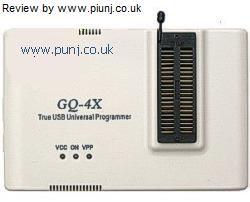
Today we are going to review the latest EPROM / EEPROM MCUmall True-USB PRO GQ-4X Willem Programmer. We will provide information on what the manufacturer of this product claims and how we recently successfully used this product to repair a failed bios on a laptop. Our review will be based on our experience on ordering this item direct from the manufacturer and its ease of use.


So what is this EPROM programmer. EPROM chips are found in numerous hardware which store essential data.

An example of this is the bios chip on all modern computers and laptops. On computers and laptops these EPROM chips will be either installed within a socket or soldered directly to the motherboard.

The bios is the first part of software code to run when you switch on a computer. This code gives instructions for the power on self test (post). This self test checks and ensures that the computer has all the required parts eg disks memory etc and that they function.

We originally had a need for a product like this for re-programming bios chips which are found in computer / laptop motherboards. We did our research like most on the Internet on what products are available, their ease of use as stated on the marketing literature and the cost of the item inclusive of shipping to our United Kingdom premises.
Most products we came across seemed very expensive and lacked the support of future software upgrades for the programmer. Also we noted that these products in most of the cases lacked good customer reviews or seemed to technical for ease of use.

One company who not only manufactures this type of product but also sells their products direct world wide is MCUmall Electronics Inc.

MCUmall Electronics Inc
is a company based in Canada which seems to have a very good reputation for the manufacture of specialist electronic hardware and software. In our own personal opinion they lead in providing budget affordable good quality hardware, the USB Pro GQ 4X would be a good example of this.

So how did we rate them on getting product information, ordering, shipping and after sales customer service on this product.

We first read their marketing literature on their web site about their EPROM programmers on this site
http://www.mcumall.com/comersus/store/comersus_dynamicIndex.asp
Their web site is simple with precise information on the products they deal with. They also have a dedicated support site which is regularly visited by their staff offering advice on not only their products but other manufacturer devices to.
After much research on this product we placed an order for the True-USB PRO GQ-4X Willem Programmer
The ordering process was straight forward like most online purchases. The order was placed in February 2010 and the cost including shipping was £84.93 GBP on our chosen payment method. We were sent emails confirming our order and shipping details.

The item took 10 working days to arrive and was well packed. The package arrived with the following contents.
1 - One True USB Programmer Series GQ-4X
2 - One USB cable, and one installation CD with the latest software and PDF user manual.
3 - One PLCC32-DIP32 Socket Adapter.
4 - One PLCC32-DIP28 Socket Adapter.
5 - One FWH+LPC Adapter.
6 - One PLCC IC extractor.

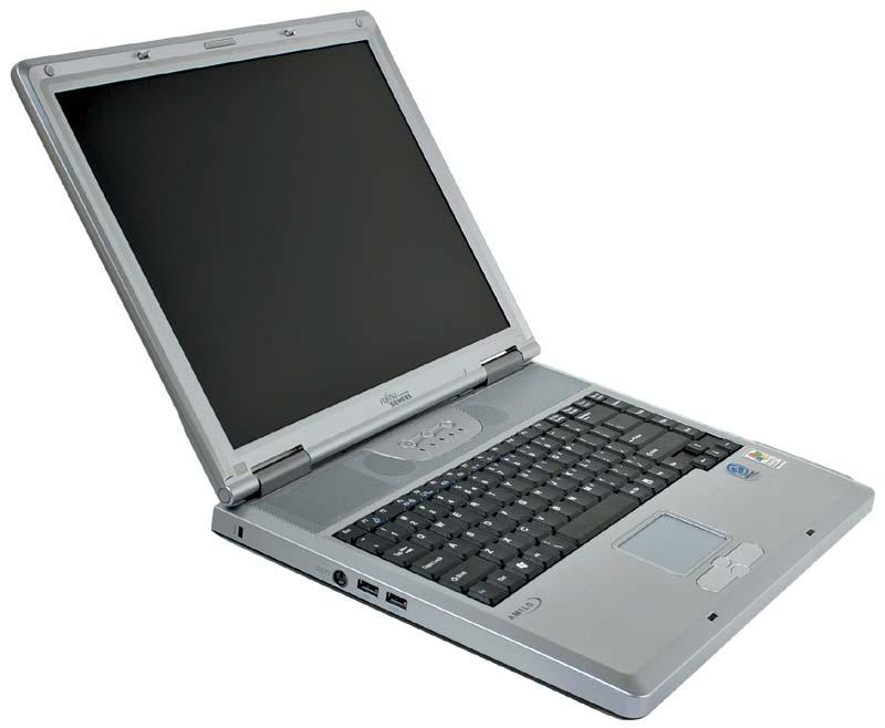
We recently acquired an Fujitsu Amilo Laptop which had a corrupt bios. The laptop was completely dead with no activity or lights on. In the past we have recovered bad bios corrupt code by using a method known as crisis disk recovery.


Most modern computer bioses can be recovered by using a crisis disk whether this be via a floppy or usb disk media. On some computers however when the bios boot tables become corrupt this can be problematic as this normally requires the bios chip to be manually reprogrammed or replaced. As the laptop showed no signs of life whats so ever we had to open the laptop casing up to get to the bios chip. For a change this laptop was quite easy to work on. The laptop bios was a plcc32 chip part number A29040AL-70.


bios


The laptop bios chip was also placed in a socket which meant it could easily be taken out. On some motherboards the bios chip can be soldered onto the motherboard which then requires the chip to be un-soldered for reprogramming or replacement. Bios eeprom programmers can be purchased with test clips that can be clipped to the chip but these are quite expensive to buy. For those who don't have an eeprom programmer the bios chips are quite cheap to buy of fleabay. The sellers can also send the chips pre-programmed with the bios code of your choice. This type of repair can be very expensive and some manufacturer support engineers sometimes replace the motherboard rather than the cheaper solution of repair or replacement of the chip. In some cases this repair can cost up to or more than the original computer itself.

Using the MCUmall True-USB PRO GQ-4X Willem Programmer device.

Using the MCUmall True-USB PRO GQUSB lead. MCUmall regularly update their software to support additional chips. If you find that your EPROM chip is not supported you can visit MCUmall support site where they will in most cases help you to add your un-supported chip to the software database.

In our review our corrupt bios chip was a plcc32 chip part number A29040AL-70. We ran the programmer software on our test computer and followed the simple instructions. The programmer software on our test machine was Revision 5.02b.
Once the software has opened you click on the "Device" tab to search for your device chip. Our bios chip was supported by the programmer software. The programmer software will then ask you to place your EPROM chip into the programmer. Clear instructions are given on placement of the chip to the programmer with regards to orientation or use of any adapter that maybe required. In our case the software asked us to place our chip in the PLCC32-DIP28 Socket Adapter and then lock the device in to the programmer ZIF socket.
You can then carry out various tasks such as read, erase, blank check, write and verify.
We already knew that the data code on our bios chip was corrupt so our first step was to delete the original code within the bios chip. We then got a copy of some good bios code from the faulty laptop manufactures web site and used this good bios data code to "write" to our bios chip. The programmer software will also verify that the new bios code has been correctly written and read from the chip.

And thats it. The process of updating our corrupt bios code was as simple as mentioned above.

To confirm that our bios chip code had been written correctly we put our bios chip back into our faulty laptop and bingo the laptop had come back to life.

In our final conclusion to our review we can honestly say that our dealings with MCUmall and the purchase of their latest MCUmall True-USB PRO GQ-4X Willem Programmer has overall been a good experience.

The company dealt with our sales order with out any prior knowledge that such a review would be made by ourselves. We have based our review solely on our experience with this great budget product with out any external influence whats so ever.

We hope our readers have enjoyed our review and will come back to www.punj.co.uk for our views on more technological products. 
 
punj


Saturday, 7 August 2010

Failed bios Amilo L6825 laptop

A friend recently gave me a Fugitsu Amilo L6825 laptop which was completely dead. He asked me to see if i could do a cheap repair or else he would buy a new one and scrap this non working laptop.


When i say dead the laptop had no indicator illumination of lights or disks spinning. My friend told me that he was on the Fujitsu support site and noted that his bios was not the current one as shown on their website. So for what ever reason he decided to update his bios on the laptop. When doing this update he encounted a problem where the laptop switched itself off during the update process. This resulted in the laptop now having a bad corrupt bios. The bios is the first part of software code to run when you switch on a computer. This code  gives instructions for the power on self test (post). This self test checks and ensures that the computer has all the required parts eg disks memory etc and that they function.
The laptop had been running Windows XP and had all his important info  on the hard disk eg emails photos etc. Normally i can recover a bad bios. Most modern computer bioses can be recovered by using a crisis disk whether this be via a floppy or usb disk media. On some computers however when the bios boot tables become corrupt this can be problematic as this normally requires the bios chip to be manually reprogrammed or replaced. My friend said that he had followed the instructions within the bios update utility but half way through the update the laptop switched its self off. As the laptop showed  no signs of life whats so ever i had to open the laptop casing up to get to the bios chip. For a change this laptop was quite easy to work on. The laptop bios was a plcc32 chip part number  A29040AL-70.
The laptop bios chip was also placed in a socket which meant it could easily be taken out. On some motherboards the bios chip can be soldered onto the motherboard which then requires the chip to be unsoldered for reprogramming or replacement. Bios eeprom programmers can be purchased with test clips that can be clipped to the chip but these are quite expensive to buy. For those who don't have an eeprom programmer the bios chips are quite cheap to buy of fleabay. The sellers can  also send the chips pre-programmed with the bios code of your choice. I however have an eeprom programmer which supports this particular chip. I have a usb pro GQ-4x supplied by a company called MCUmall Electronics in Canada.
I was able to use my eeprom programmer to re-program the bios code back on to his existing chip. On completing the bios recovery the laptop was fully recovered. My friend was amazed and very grateful for having his laptop bought back to life. The most important thing was he was able to get his precious data back.

On giving his laptop back to him i gave him that most important advice "If it ain't broken don't fix it".  i couldn't understand why he needed to update the bios in the first place. 

This type of repair can be very expensive and some manufacturer support engineers sometimes replace the motherboard rather than the cheaper solution of repair or replace the chip. In some cases this repair can cost up to or more than the original computer itself.
 
As this was a repair for a friend this cost him just one hours labour.

--Another gadget saved from the ever growing landfill--

Check for more updates at www.punj.co.uk

punj

Friday, 6 August 2010

Wireless router problems

I recently had someone having problems with a Netgear RangeMax Dual Band Wireless N Router Model WNDR3300. The problems reported were that the wireless connection was always intermittent. The client workstations would keep on connecting and then in a short time disconnect from the router. The signal bar on the workstations were also constantly going up and down.
After ensuring that the router had the latest firmware it was assumed that the router maybe experiencing some interference which may be effecting the wireless network. The router setup menu was accessed and it was noted that the wireless channel was set on the auto channel.
We then decided to set the channel setting to channel 2. Once the router had been re-booted it was noted that 5 of the 6 workstations now had good wireless signal and a very satisfactory connection.

We then worked on the 6th workstation which was a HP laptop. First of all we checked the HP website to ensure that we had the latest wireless drivers installed. Then we checked for a suitable connection by means of connecting by a hard wired Lan connection.

We noted that the laptop would work via the Lan connection but the browser seemed some what slower in response compared to the other work stations. Our next approach was to check our anti virus software for updates. We then noticed that this laptop had been running without any anti malware / spyware utility.

The laptop was then installed with a free popular anti spyware utility and checked for undesirable infections. When the program completed we noted that it found numerous infections. We opted for our program to delete all infections found. After re-booting the wireless connection on the laptop seemed to have been repaired.

So in the final summary our wireless network seemed all of a sudden not to like the default channel that it was set on. This was rectified by setting the channel to channel 2. It was assumed that some interference was probably being picked up which we were unable to identify. The laptop had been proven to contain malicious malware activity which played havoc on the working of the router and laptop.

For people with similar problems our advice would be to ensure that your wireless network is not prone to interference and the most important advice do ensure that your security anti-virus and anti-malware software are up to date.

Check for more updates at http://www.punj.co.uk

punj

Tuesday, 3 August 2010

Amstrad DRX180 Sky+ Box

I was asked to look at an Amstrad DRX180 Sky+ PVR satellite box. The problems that the user reported was that the box was giving a "No signal" on tuner 2. This prevented him to record a different channel to the one being watched.

The box was out of warranty and sky in his opinion was charging a lot of money to send an engineer out to have a look at his box. Sky had quoted him for replacement reconditioned box.

I opened the case and immediately noticed a 470uf 16v capacitor quite local to the tuner with a bulging case. The capacitor was un-soldered and replaced with a 470uf 25v capacitor.

Replacement of this capacitor satisfactorily repaired the box. On researching these symptoms further on google it seemed that this type of problem of no signal on tuner 2 was quite common on this particular type of box. Sometimes this was repaired by replacing the hard disk drive. The hard disk on this box seemed ok as once the capacitor had been replaced the recording seemed to work.

The cost of the capacitor was a few pence.
--Another device repaired by replacement of a capacitor costing a few pence--
Check for more updates at  http://www.punj.co.uk

punj

Monday, 2 August 2010

Linksys 12v 1A power supply unit causing havoc on DSL line

Recently i was given a Linksys 12 volt 1000mA power supply unit which had been causing havoc to a users dsl connection. The user over a period of a few weeks had noticed his dsl  router connection to randomly re-sync causing the isp's DLM system lowering his connection speed. At first it was thought that there was a line fault as there was sometimes a buzzing noise being heard on the telephone line. The user  reported a fault to his telephone service provider. After a few days the telephone company's engineer had diagnosed the problem to be the user's equipment. I was called to see if i could help.
The fist thing i did was to go into the routers web configuration page to look at his router stats. I noticed that the router had been re-syncing multiple times and the line stats were very bad as well.  The DL noise margin had crept up to 15db and the line attenuation of 36db didn't reflect to the lousy line rate of 800kbps.
To eliminate equipment i first tried a spare replacement belkin router. This immediately improved the line stats and line rate. So it was thought that the Linksys router was probably the cause of his problems and would probably be best to replace.
As the user was going on his annual holiday he asked me to repair or find a replacement router. I opened up the router and could not see anything wrong. Then i tried a replacement power supply and the router immediately was showing a more appropriate line stats.
So the problems was the power brick power supply. I decided to crack open the power supply.


The power supply was very basic consisting of a transformer, a pcb with four diodes and a smoothing capacitor. I tested the transformer on the secondary side which was giving out approx 17V under no load which seemed correct. I then tested the four diodes on the pcb which two tested unsatisfactory. The 2200uf smoothing capacitor also showed a capacitance reading of 83uf with an esr reading of 19.5 which defiantly was a sign of failure.
I replaced all four of the diodes with some spare IN5400 and soldered a new 2200uf 25V capacitor. The casing was glued back and the router and repaired power supply put back on the user's dsl line.
The results were a complete success as the sync rate immediately jumped up to a more respectable 7345kbps and the line noise lowering itself to 7db.
The cost of the the components replaced were under two British pounds and the client recently reported that he has never had his router work so well.

-- Another piece of electronic equipment saved from a journey to the ever growing landfill --
Check for more updates at  http://www.punj.co.uk

punj

Sunday, 1 August 2010

ESR Micro capacitor test meter

Read this blog contents also at    http://www.punj.co.uk/punjwebfiles/electronics/microesr.html
*Permission granted to post above link by the website owners at http://www.punj.co.uk*
 
Well anyone who dabbles alot in electronics will tell you that it can be very useful to have an esr meter to test for bad capacitors. When the hobbyist then researches to get one of these handy items for the toolkit they can be quite expensive and sometimes quite difficult to understand. So what is esr and its revelances on a  capacitor.

ESR can be explained as follows. A capacitor consists of metal plates, which are filled with a dielectric that separates the plates consisting of an oxide layer on the lining, and the electrolyte. All this is placed in an aluminum at the connection plates. This, in turn, causes resistance to form a pathway deterioration for the alternating current within the capacitor, causing heat, and consequently, accelerates the processes described above. All losses may be summarized in the so-called equivalent series resistance (ESR) - an imaginary resistor in series with the capacitor itself.
When you google esr meter for info on these items you will find quite a few. I found that these meters can be quite expensive and also not very user friendly for the lame hobbyist.

I however came along one such meter which was not only within my tight budget but very user friendly to use.
The esr meter that i found on google and bought was a little device called EsrMicro V4.
This little device was purchased from Russia http://www.radiodevices.info/zakaz_e.php
At the time when i bought this it cost 75US Dollars which included taxes and shipping. If you need one you just fill out the order form and a chap called Mike will email you back on how to complete your order.  I also found Mike very good at communicating with any queries relating to the product or order.
Mike also frequents occasionally at the http://www.badcaps.net/  where he has acquired a very good reputation. Just do a search for esr meter on the site and you will note the very happy customers around the world he has sold these meters to.
The order took 10 days for delivery which is not bad for delivery to the UK. The meter will come without batteries and a very basic manual. 
Using the meter is very easy. You can use the meter probe lead or you can use the meter socket pins to check a capacitor. The meter will give a very clear reading of the esr reading and the capacitance reading.
One very important thing to bear in mind is that you must ensure that when testing existing capacitors that they have been fully discharged. The meter incorporates only a very simple protection by the use of diodes. This minor protection against a capacitor discharging on the meter can quite easily cause major damage to the meter. But comparing this to other meters which can literally cost hundreds of dollars if you ensure that you carryout discharging of your electronic component capacitors this meter will serve you well.
I have now used this meter a few times and can say it greatly helps in the diagnostics of my electronic projects very well.

I will in time post further blogs on how this meter helped and the kind of bad readings of a capacitor which can only be found by using such instruments as this.
 
---Hope this was a good read ---

Read this blog contents also at    http://www.punj.co.uk/punjwebfiles/electronics/microesr.html
*Permission granted to post above link by the website owners*

punj

Saturday, 31 July 2010

Our repairs on a DVD player with bad capacitors

Over the years like most people i have noted that electronic gadgets just don't seem to last that long. I have replaced tv's, video players, dvd player etc. In the past i have just threw the faulty goods into the the great ever increasing landfill. These days however we have to think about our environment and take responsibility for the world we live in.
The Internet and world wide web has proved to be so useful in enhancing our knowledge and sharing interests and experiences. Indeed you can find new hobbies and learn about almost any subject.
I've  done just that in the past. Recently  one of our long serving DVD players decided to just die completely on us. This player had served us well and was over five years old.
The symptoms was just a red flashing light at the front of the dvd player and everything else completely dead.
Matsui DVD225
On opening the case i noted that dreaded electronic disease "bad caps". The Internet is full of reports on this type of failure and by googling just "bad caps" you will find many topics on this subject. The bad cap problem seems to have effected every kind of electronic device.
On opening the case of our DVD the main power supply PCB had 3 bulging capacitors. On close examination with a magnifying glass you could also see that 2 of the capacitors had leaked their contents onto the PCB.
The next thing to do was to un-solder those bad capacitors. I used my new 30w soldering iron with one of those solder suckers to remove the bad caps. The faulty caps were rated 1000uf, 470uf and 220uf with a voltage rating of 16v. I had some new Rubycon capacitors of the same capacitance value and a voltage rating of 25volts. I carefully soldered the new caps closely baring in mind the correct polarity. Then after putting the case back on and switching on was very pleased to see the dvd player come back to life.
The whole repair excluding my own labour rates was under a few UK pounds. And the time of the full repair was less than half an hour.
The most joyful experience is the satisfaction of repairing and learning along the way.

I have also recently purchased one of those esr meters for testing capacitors and will blog info on this soon. The meter i purchased for my basic electronic tool kit was very good quality purchased from the internet but also very reasonably priced.

Hope you have enjoyed my blog today and don't forget feel free to leave any comments below.
Check for more updates at  http://www.punj.co.uk

punj